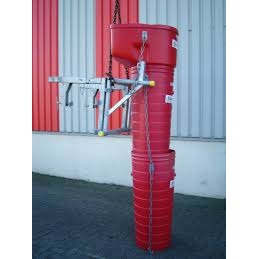
Inlet chute support frame Rent
Product Features
Description
Rental rates including VAT and deposit
-
Per day: €4
-
Weekend (Saturday morning pickup, return by Monday morning before 9 am): €6
-
Per week: €12
-
Deposit: €25
Weekend
The weekend rental starts on Saturday morning, with the item to be returned by Monday morning before 9 am. If the item is returned before 9 am on Monday, the rental period and rate will be adjusted from 2 days to 1.5 days.
General Information
The support frame for hanging the inlet chute is only available for rental in combination with the set of window holders.
Instructions
How to assemble an inlet chute?
Inlet chute assembly banner.
What is an inlet chute?
Before we explain how to assemble an inlet chute, let's first take a look at the inlet chute itself. What does it consist of? A complete rubble chute typically includes the following elements:
-
Chutes in the form of a blunt cone made of plastic or galvanized steel, with connections via chains, hooks, and eyes.
-
A support frame (draagbok) for attaching a hand winch and hanging the chutes. The support frame must be attached to a window frame or scaffolding.
-
Window attachments that grip the parapet like a clamp and support the chute.
-
A hand winch with a support frame that is exclusively used for the assembly and disassembly of the chutes (lifting the chutes from the ground).
-
Note: Only original Müba construction components may be used for the chutes!
General Setup of the Inlet Chute
-
The maximum height for a plastic chute – such as ours – is up to 40 meters. If the chute is made of galvanized steel, the maximum length is 30 meters. When attaching the chute to masonry, the maximum height or length is 25 meters.
-
The chute must be pulled vertically and hung vertically in operational mode. Chutes with an intermediate filler must be mounted completely vertically. The construction components of the rubble chutes are designed for maximum tilt during assembly and disassembly, with a maximum play in operational mode of 10:1 (10 meters vertical, 1 meter horizontal).
The stability approval takes into account the following:
-
The weight of the entire construction.
-
2 meters of rubble filling to account for blockages.
-
Wind load according to DIN 1055 part 4.
-
Horizontal forces from tilt and freedom of movement of 10:1 (10 meters vertical, 1 meter horizontal).
Attaching the Inlet Chute to a Window Opening
Window attachments consist of two load-bearing elements with a distance of 740 mm:
-
Support spindle
-
Telescope arm
-
Bolt alignment
-
Load distribution (inside)
-
Load distribution (outside)
-
Support surface for the support frame
-
Connection for the support frame
Support Frame for Inlet Chute
The forces transferred to the walls must be demonstrated by the user of the inlet chute in each individual case!
Assembly Instructions for Masonry Structures:
-
The maximum installation height of the chutes for masonry is 25 meters.
-
The extension length of the inner support spindle (1) and alignment for the bolts (3) in the telescope arm (2) depend on the thickness of the wall.
-
The bearing forces from the supports on the inside and outside of the masonry (parapet) must be transferred into the rising walls, at least 36 cm thick, to the left and right of the parapet.
For this, it is necessary to use inside (4) and outside (5) transfer elements (e.g., horizontal braces) of sufficient size for load distribution with the required length. These must be secured against displacement and falling.
Assembly Instructions for Concrete Structures:
-
The maximum installation height for concrete and sufficiently reinforced wall parts is 30 meters for steel chutes and 40 meters for plastic chutes.
-
The assembly of window attachments, consisting of two load-bearing elements, is done like in masonry constructions using transfer elements for load distribution.
These may be omitted if, in the individual case, proof can be provided that the concrete wall parts alone can absorb the forces applied.
Mounting the Inlet Chute on a Scaffolding
The support frame is attached to crossbars R, which must be positioned symmetrically in height with respect to the scaffolding position.
The posts in the connection range (A, B, C, respectively A, B, according to floor plan) must be anchored to the building where the support frame is attached. If existing scaffolding anchorages are used, the anchoring forces from the chute must be considered in addition to those from the scaffolding system.
Mounting the Inlet Chute on a Standard Scaffolding
-
The scaffold holders must be attached to the inside and outside posts. Attaching only to the inside posts is allowed if the transfer of horizontal forces parallel to the scaffolding plane is guaranteed by other measures – e.g., horizontal braces.
-
When mounting the inlet chute on a standard scaffold, the chute must be attached parallel to post pair II. Scaffold braces R with a tube diameter of 48.3 mm are required. These must not be inserted and must be attached to the posts with standard scaffolding couplers marked with certification B.
Inlet Chutes with Intermediate Anchors
-
If your inlet chute is less than 10 meters in length, it can be hung without intermediate anchors. However, if your inlet chute is longer than 10 meters, intermediate anchors are required at a maximum distance of 8 meters.
-
These intermediate anchors depend on the conditions of the construction and can only be determined in individual cases. Proof of stability must also be provided in the individual case.
Instructions for the Use of Your Inlet Chute
-
Lifting and lowering the inlet chute is only allowed up to wind force 6.
-
Operational attachments via couplings must be made immediately after reaching the final installation position and may only be removed just before the start of disassembly.
-
The inlet chute must not be hanging on the winch in operational mode. The winch should only be used for lifting and lowering the chute during (de-)installation.
-
When lowering the inlet chute, at least two turns of the cable must remain on the winch drum.
-
The lifting and lowering of the chute must always be done vertically.
-
If the attachments are strong enough, a tilt of up to 10:1 is allowed as an exception (1 meter horizontal, 10 meters vertical).
-
No parts longer than the smallest diameter (400 mm) may be thrown into the chute.
-
In case of blockages, the rubble supply must be immediately stopped. To resume, the blockage must be cleared.
-
After blockages, all load-bearing components, especially chains, carabiners, links, upper load-bearing constructions, and window and scaffolding attachments, must be checked for damage and permanent deformations. Damaged parts must be replaced!
Extra product options
Plastic rubble chute
1 Day € 8,00
1 Week € 24,00
Including VAT
Plastic rubble chute
chute inlet
1 Day € 10,00
1 Week € 30,00
Including VAT
chute inlet
Chute window holders
1 Day € 4,00
1 Week € 12,00
Including VAT


